Model (4 of 4)
Note:
You can download a .pdf file of this page here.
Front
Press NUMPAD-1, NUMPAD-6 three times and NUMPAD-8 twice to position building.
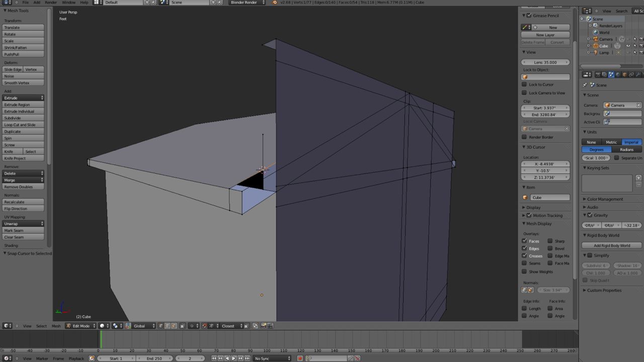
Remove the excess edges as shown in the figure below.
Press NUMPAD-4 to rotate to the left side and remove the excess edges as shown
in the figure below.
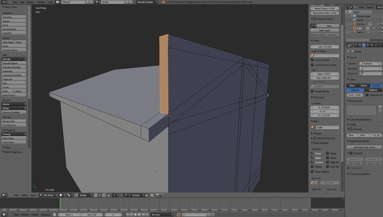
Now we have some vertices to move and some vertices to place at the
intersection of two edges, procedures you should be quite familiar with by now.
Switch to Wireframe Mode (Z-KEY). Select the upper side edge and subdivide (Q-
KEY). Using Snap during Transform, move the vertex to six inches from the front
(G-KEY then Y-KEY).
Duplicate the vertex (SHIFT + D then ENTER), move (G-KEY) it upwards (Y-KEY) to
above the roof line by dragging, and join (F-KEY) the two vertices.
Switch to Solid Mode (Z-KEY) and Edge Select Mode (2-KEY), select the two
intersecting edges and move the cursor to the point of intersection (SPACEBAR
the C-KEY, then E-KEY). Subdivide the roof edge (Q-KEY) and move the new
vertex to the point of intersection (SHIFT + S-KEY then T-KEY). Remove the
vertical edge at the intersection (2-KEY then X-KEY then E-KEY).
Select the two front intersecting edges. Place a vertex at the point of
intersection. Join the two new vertices and fill in the adjoining faces.
Rotate the model and fill in face on the back side of the facade.
Repeat the process for the right side of the building front.
Save your file ( in my case "Slice_and_Dice10.blend" ).
Front Steps
The front steps are an add-on, i.e., were not included within the block of "clay"
when we started out. Sometimes it is more convenient to add features to the
model rather than take the "slice and dice". The front steps are an example. We
could model these by extending the appropriate portions of the front side.
However, I have chosen to "stick" build them.
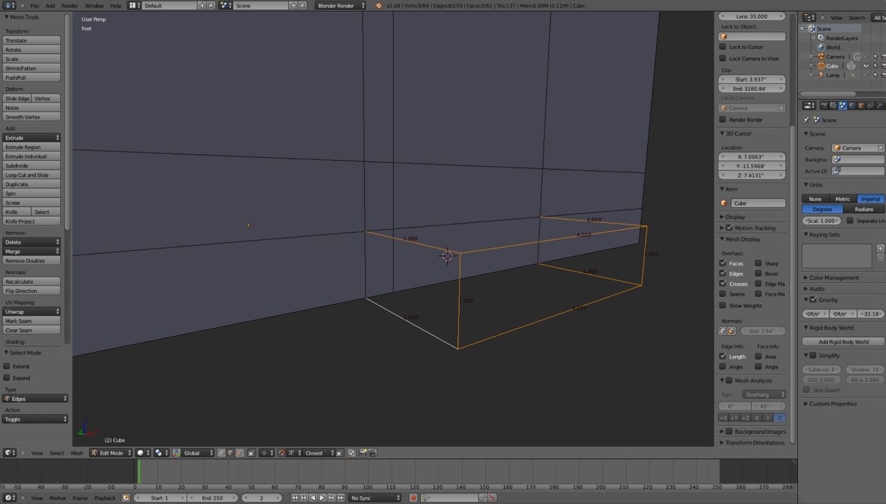
Switch to Vertex Selection Mode and select the lower left corner vertex of the
steps. Press SHIFT + D-KEY then ENTER to duplicate the vertex. With the vertex
selected press the G-KEY and the Y-KEY to constrain the movement to the Y-axis,
then type "-0.6". Join the two vertices. If you turn Edge length back on in ht
Properties Viewport you will see that the new edge of the lower step is
approximately two feet long.
By duplicating the other three corners and joining the vertices complete the
formation of the bottom step.
Use the subdivide function to divide the upper edges of the bottom step and the
duplicate function to form the outline of the upper step moving the vertices out
"-0.3" or approximately one foot. Fill in the faces to complete the steps.
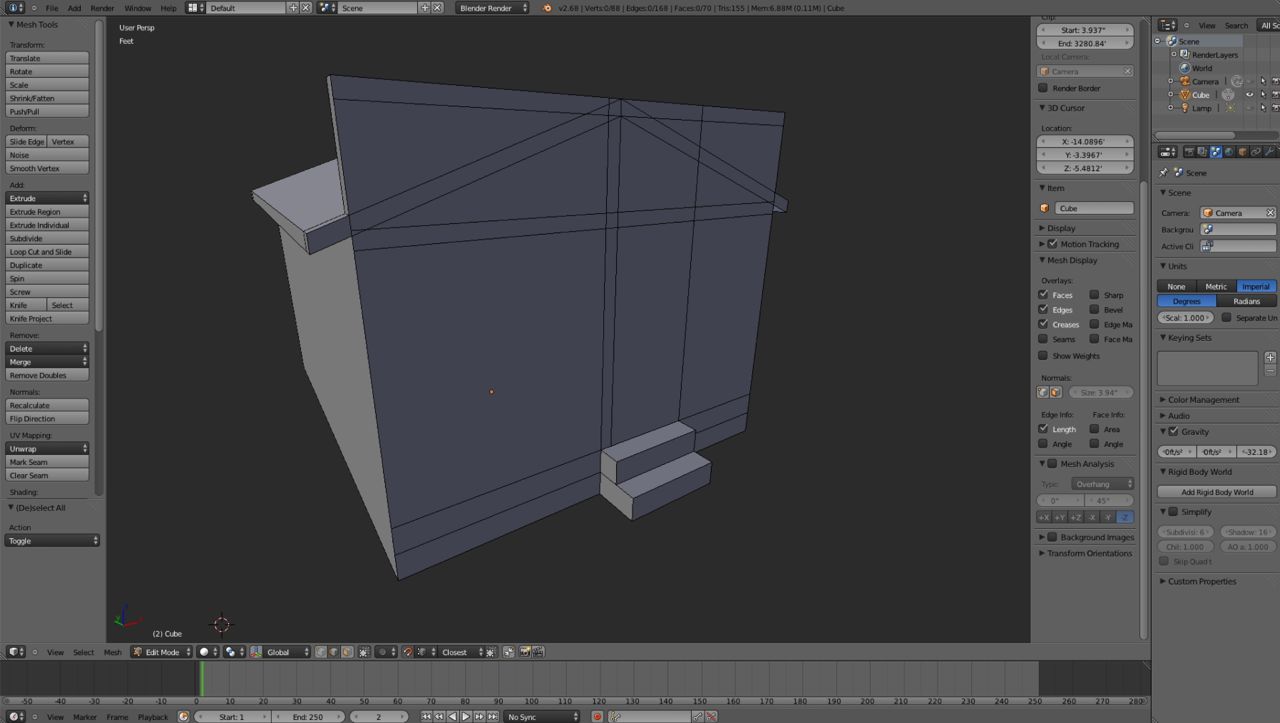
Cleaning up the Model
The Slice and Dice approach facilitates laying out and shaping a model, or at
least the basic form of the model. However, it can and does leave a number of
unnecessary and unwanted vertices, edges and faces. Ideally these should be
removed to keep the polygon count of the model as low as possible. The figure
below illustrates the degree to which faces can be reduced on the front.
In Edit Mode by selecting the whole model (A-KEY) and pressing "Remove
Duplicates in the Tool Shelf panel the model may be cleaned up even further. My
finished model has 32 faces which is approximately 64 polys (polygons).
Save your file ( in my case "Slice_and_Dice11.blend" ).